Our 4-Axis CNC Machining Services
Elevate your cylindrical and multi-sided part production with our 4-Axis CNC Machining services—the perfect blend of 3-axis precision and rotary axis (A/B Axis) versatility.
Ideal for aerospace, automotive, and medical industries, we deliver complex geometries (gears, shafts, brackets) across metals (titanium, stainless steel) and non-metals, with reduced setup time, consistent results, and cost-effective solutions. Turn your multi-feature designs into high-quality parts—fast.
Our 4-Axis CNC Machining Capabilities
We offer robust machining capabilities tailored to 4-axis systems, with a focus on rotary table capabilities and precision for complex parts. Below is a detailed breakdown of our key capacities, including maximum part size, material thickness, precision levels, custom machining, and tolerance achievements:
| Capability | Specification |
| Axes Configuration | 3 linear axes (X: 1200mm, Y: 800mm, Z: 600mm) + 1 rotary axis (A or B; 360° continuous rotation) |
| Maximum Part Size | – Diameter: Up to 500mm (for cylindrical parts)- Length: Up to 1000mm (for shaft-like parts)- Weight: Up to 500kg (supported by heavy-duty rotary tables) |
| Material Thickness | – Metals: Up to 150mm (stainless steel), 200mm (aluminum), 100mm (titanium), 180mm (brass)- Non-Metals: Up to 250mm (plastics), 200mm (composites), 150mm (wood) |
| Precision Levels | – Linear axes: ±0.01mm- Rotary axis: ±0.005° (angular precision) |
| Custom Machining | – Complex features: Slots, holes, chamfers on cylindrical surfaces- Compatibility: CAD/CAM files (DXF, DWG, STEP, STL)- Volume: Prototypes (1–50 units) to high-volume (30,000+ units/month) |
| Tolerance Achievements | Meets ISO 2768-1 (fine grade); critical parts (e.g., aerospace shafts) achieve ±0.008mm linear tolerance and ±0.003° rotary tolerance |
| Rotary Table Capabilities | – Speed: Up to 200 RPM (for high-speed cutting)- Clamping force: 8000N (secures heavy parts)- Indexing: 0.001° incremental steps (for precise positioning) |
Whether you need to machine a single titanium shaft or 10,000 brass gears, our 4-axis capabilities scale to match your project’s complexity and volume.
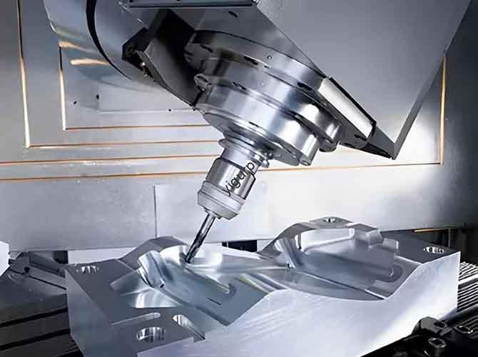
What Is 4-Axis CNC Machining?
4-Axis CNC Machining is an advanced manufacturing technology that builds on 3-axis machining (X, Y, Z linear axes) by adding a rotary axis (A or B Axis)—a rotating table that spins the workpiece around one of the linear axes. This extra axis lets the machine access multiple sides of a part in a single setup, eliminating the need for manual repositioning and unlocking more complex geometries than 3-axis systems.
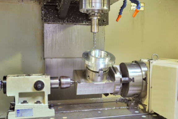
The process overview is straightforward: A CNC (Computer Numerical Control) system interprets CAD designs to synchronize the linear axes (X/Y/Z, controlling the cutting tool) and the rotary axis (controlling the workpiece’s rotation). The two common rotary axis configurations are:
- A-Axis: Rotates the workpiece around the X-axis (ideal for long, cylindrical parts like shafts).
- B-Axis: Rotates the workpiece around the Y-axis (better for shorter, irregularly shaped parts like brackets with multi-sided features).
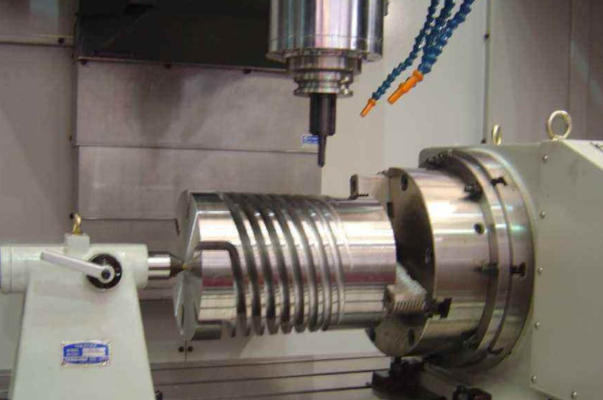
To explain “how it works” simply: Imagine a 3-axis machine that can spin your part like a rotisserie while cutting it. For example, when making a gear, the 4-axis machine cuts the gear teeth on the outer circumference as the rotary axis turns the part—all in one run, no need to stop and reposition. This is the core value of 4-Axis CNC Machining: combining linear precision with rotational flexibility to streamline production of multi-sided parts.
The 4-Axis CNC Machining Process
Our step-by-step process is optimized to leverage the rotary axis for efficiency and precision, from design to finished part:
- Design and CAD Modeling: We start by reviewing your CAD model (or creating one from sketches). Our engineers focus on optimizing the design for 4-axis machining—e.g., ensuring features on cylindrical surfaces are aligned to the rotary axis to avoid unnecessary setups. For prototypes, we offer free design feedback to improve manufacturability.
- CAM Programming: The CAD model is imported into CAM software (Mastercam, SolidWorks CAM), where we program tool paths for both linear and rotary axes. We synchronize the rotary axis rotation with linear tool movements—for example, programming the A-axis to spin 90° while the Z-axis lowers the cutting tool to add a slot on a shaft’s side.
- Setup and Calibration: The workpiece is clamped to the rotary table (custom fixtures are used for irregular shapes). We calibrate the rotary axis using laser measuring tools to ensure alignment with linear axes (critical for precision). Cutting tools (e.g., end mills, drills) are loaded, and coolant systems are activated to prevent overheating.
- Machining Execution: The CNC system runs the program, synchronizing linear (X/Y/Z) and rotary (A/B) movements. For example, when machining a gear, the rotary axis spins the part at a steady speed while the X/Y axes move the cutting tool to cut teeth. We monitor the process in real time to adjust speeds or coolant flow if needed.
- Post-Machining Inspection: After machining, parts undergo rigorous checks. We use CMMs (Coordinate Measuring Machines) to verify linear dimensions and angular measurements (for rotary axis features). Parts with rough edges move to deburring or grinding for finishing.
- Rotary Axis Integration Review: For complex parts, we review the rotary axis performance (e.g., rotation smoothness, positioning accuracy) to refine future programs—ensuring consistent quality for repeat orders.
Materials We Work With
4-Axis CNC Machining excels with both conductive and non-conductive materials, with particular strength in machining cylindrical or multi-sided parts. Below is a breakdown of our supported materials, their key properties, and ideal uses:
| Material Category | Examples | Key Properties | Ideal Applications | Machining Notes |
| Metals | Stainless Steel | Corrosion-resistant, strong | Medical instrument shafts, marine gears | Use carbide tools; high-pressure coolant reduces heat |
| | Aluminum | Lightweight, easy to machine | Automotive suspension parts, aerospace brackets | Fast cutting speeds; minimal tool wear |
| | Titanium | High strength-to-weight, heat-resistant | Orthopedic implant stems, aircraft shafts | Slow speeds; sharp tools prevent tool wear |
| | Brass | Malleable, conductive | Electrical connectors, gear hubs | Fast speeds; produces smooth finishes |
| | Copper | Highly conductive, soft | Heat exchanger tubes, electrical terminals | Use coolant to avoid melting; sharp tools for clean cuts |
| Non-Metals | Plastics (ABS/Polycarbonate) | Lightweight, durable | Electronics casings (with side holes), prototype gears | Low speeds to prevent warping |
| | Composites | High strength, lightweight | Racing car drive shafts, drone frames | Specialized carbide tools to avoid fiber fraying |
| | Wood | Natural, cost-effective | Custom furniture legs (turned designs), decorative columns | Sharp tools; vacuum fixtures secure parts |
We test all materials to optimize cutting speeds, tool selection, and coolant use—ensuring consistent results across every part.
Tolerances & Quality Assurance
Tolerances and accuracy standards are critical for 4-axis parts—especially those with features on rotating surfaces (e.g., gear teeth, shaft holes). Our precision levels and tolerance ranges are tailored to your material and application, with a focus on rotary axis precision:
| Material | Linear Tolerance (X/Y/Z) | Rotary Axis Tolerance (A/B) | Accuracy Standard Used | Measurement Technique |
| Stainless Steel | ±0.01mm | ±0.005° | ISO 2768-1 (fine), ASME Y14.5 | CMM + Angular Laser Scanner |
| Aluminum | ±0.015mm | ±0.008° | ISO 2768-1 (fine), AMS 2750 | CMM + Digital Protractor |
| Titanium | ±0.012mm | ±0.006° | ISO 2768-1 (fine), AMS 4928 | CMM + Optical Comparator |
| ABS Plastic | ±0.02mm | ±0.01° | ISO 2768-1 (medium), ASTM D638 | CMM + Micrometer |
| Composites | ±0.025mm | ±0.012° | ISO 1288-1, ASTM D3039 | CMM + Profilometer |
Our quality control processes include:
- Pre-machining: Inspecting raw materials for defects (e.g., cracks in titanium, unevenness in composites) and verifying dimensions.
- In-process: Monitoring rotary axis alignment and tool paths in real time via CNC software; periodic checks with calipers and protractors.
- Post-machining: 100% inspection with CMMs (for linear and angular dimensions); critical parts (e.g., aerospace shafts) undergo additional testing (e.g., runout checks, fatigue tests).
Documentation: We provide a detailed quality report with every order, including linear/rotary tolerance data, inspection results, and compliance certificates (ISO 9001, FDA for medical parts).
Key Advantages of 4-Axis CNC Machining
Compared to 3-axis machining (which requires multiple setups for multi-sided parts) and 5-axis machining (which is more costly for simple complexity), 4-Axis CNC Machining offers balanced benefits:
- High Precision: With linear tolerances as tight as ±0.01mm and rotary axis precision of ±0.005°, it produces parts that fit seamlessly—critical for gears, shafts, and medical implants.
- Complex Geometries: The rotary axis enables machining of features on cylindrical or multi-sided parts (e.g., slots on a shaft, holes on a gear hub) that would require 2–3 setups with 3-axis systems.
- Reduced Setup Time: One setup handles all sides of a part—cutting setup time by 50–70% compared to 3-axis machining. For high-volume orders (e.g., 10,000 automotive parts), this translates to faster production.
- Increased Efficiency: Fewer setups mean less operator time and fewer errors (e.g., misalignment from repositioning). Our clients report 30–40% faster production times for multi-sided parts.
- Versatility: It works with all common metals and non-metals, and handles both simple (brackets) and complex (gears) parts—making it a one-stop solution for diverse projects.
- Cost-Effectiveness: More affordable than 5-axis machining (lower equipment and operational costs) while offering more capability than 3-axis. Reduced setup time and errors also lower labor and material waste costs.
- Consistency and Repeatability: CNC programming ensures every part is identical—critical for replacement parts (e.g., aerospace shafts) or mass-produced components (e.g., brass connectors).
- Rotary Axis Benefits: The continuous rotation of the A/B axis enables high-speed machining of cylindrical parts (e.g., gears) and precise indexing for multi-sided features (e.g., a bracket with holes on 4 sides).
Industry Applications
4-Axis CNC Machining is widely used across industries that need multi-sided or cylindrical parts. Here are its most common applications:
| Industry | Common Uses | Key Benefit of 4-Axis Machining |
| Aerospace | Shafts, turbine components, brackets with side holes (aluminum/titanium) | Reduced setup time for high-precision parts |
| Automotive | Gear hubs, suspension parts, drive shafts (steel/aluminum) | Consistency for mass production |
| Medical Devices | Orthopedic implant stems, surgical tool shafts (titanium/stainless steel) | Precision for patient-specific fits |
| Industrial Manufacturing | Conveyor rollers, pump shafts, gearboxes (steel/brass) | Versatility for diverse part types |
| Electronics | Connector housings (brass), heat sink brackets (aluminum) | Ability to machine side holes in small parts |
| Defense | Weapon components, vehicle armor brackets (steel/titanium) | Durability and precision for critical parts |
| Tool and Die Making | Mold cores with side features, die inserts (steel) | Complex geometry capability |
| Prototyping | Rapid prototypes of gears, shafts, and multi-sided brackets (plastics/aluminum) | Fast setup for low-volume runs |
For example, in the automotive industry, our 4-axis machining produces 10,000 gear hubs monthly with consistent tooth spacing—thanks to the rotary axis’ precise indexing. In medical devices, we machine titanium implant stems with side slots (for bone screws) in one setup, ensuring patient-specific precision.
Case Studies: Success Stories
Our 4-Axis CNC Machining services have helped clients across aerospace, automotive, and medical industries solve complex production challenges. Below are two successful projects showcasing our expertise in leveraging the rotary axis for efficiency and precision:
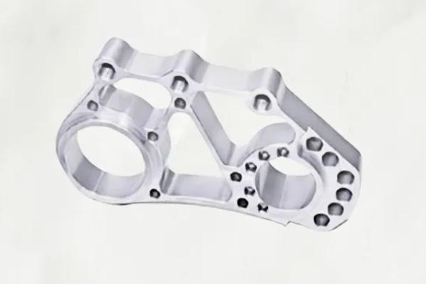
Case Study 1: Automotive Gear Hub Manufacturer
- Challenge: The client needed 10,000 brass gear hubs monthly for electric vehicle transmissions. Each hub required a turned outer diameter, 6 radial holes (evenly spaced at 60°), and a milled keyway—all with a tolerance of ±0.01mm. Their previous supplier used 3-axis machining, which required 3 setups (turning, drilling, milling) and caused 8% of parts to fail due to misalignment (holes not centered on the hub). Lead time was 3 weeks, which delayed their EV production.
- Solution: We used 4-axis CNC machining with A-axis (rotary around X-axis) to complete the hub in one setup. First, we turned the outer diameter using continuous rotary rotation; then, we indexed the A-axis to 60° increments to drill the radial holes (ensuring perfect spacing); finally, we milled the keyway by synchronizing A-axis rotation with X/Y linear movement. We used carbide turning inserts and flood coolant to handle high-volume production, and optimized tool paths to cut each hub in 2 minutes (down from 5 minutes with 3-axis).
- Results:
- Misalignment rate dropped from 8% to 0.5%—only 50 parts failed per month (vs. 800 previously).
- Lead time shortened from 3 weeks to 10 days—helping the client meet their EV assembly schedule.
- Production cost per hub decreased by 30% (reduced labor from fewer setups and faster cutting time).
- Client Testimonial: “The 4-axis machining transformed our gear hub production. One setup eliminated misalignment, and the faster speed let us keep up with EV demand. We’ve expanded our order to 15,000 hubs monthly!” — Lisa M., Automotive Production Manager.
- Before and After: 3-axis hubs had uneven hole spacing and off-center keyways; 4-axis hubs featured perfectly aligned holes and keyways that fit seamlessly into transmissions.