Our Multi-Axis CNC Machining Services
Unlock the potential of complex, high-precision parts with our Multi-Axis CNC Machining services—the gold standard for crafting intricate geometries across aerospace, medical, and automotive industries.
From 3-axis milling to 5-axis turning, we deliver unmatched precision, reduced setup time, and consistent results for metals (titanium, stainless steel), composites, and plastics. Whether you need prototypes or high-volume production, our tailored solutions boost efficiency, cut costs, and turn your most ambitious designs into reality.
Our Multi-Axis CNC Machining Capabilities
We offer comprehensive machining capabilities across 3-axis, 4-axis, and 5-axis systems to meet diverse project needs. Below is a detailed breakdown of our key capacities, including maximum part size, material thickness, precision levels, custom machining, and tolerance achievements:
| Capability | Specification |
| Axes Coverage | 3-axis (milling/turning), 4-axis (rotational A-axis), 5-axis (A+B/C axes) |
| Maximum Part Size | – 3-Axis: 1200mm × 800mm × 600mm- 4-Axis: 1000mm × 600mm × 500mm- 5-Axis: 800mm × 500mm × 400mm |
| Material Thickness | – Metals: Up to 200mm (stainless steel), 150mm (aluminum), 100mm (titanium)- Non-Metals: Up to 300mm (plastics), 250mm (composites), 200mm (wood) |
| Precision Levels | – 3-Axis: ±0.01mm- 4-Axis: ±0.008mm- 5-Axis: ±0.005mm |
| Custom Machining | – Complex 3D geometries (e.g., undercuts, curved surfaces)- CAD/CAM compatibility (DXF, DWG, STEP, STL files)- Low-volume prototypes (1–50 units) to high-volume production (50,000+ units/month) |
| Tolerance Achievements | Meets ISO 2768-1 (fine grade) for all axes; 5-axis parts achieve ±0.003mm for critical aerospace/medical components |
Whether you need a simple 3-axis bracket or a 5-axis turbine blade, our capabilities scale to match your design’s complexity.
What Is Multi-Axis CNC Machining?
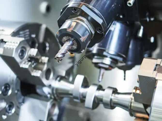
Multi-Axis CNC Machining is an advanced manufacturing technology that uses computer-controlled machines with multiple axes of motion to shape raw materials into complex parts. Unlike traditional 2-axis machining (limited to length/width), it adds rotational axes to manipulate the part or cutting tool—enabling seamless fabrication of 3D geometries that would be impossible with fewer axes.
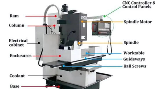
The process overview is intuitive: A CNC (Computer Numerical Control) system interprets design files to guide the machine’s axes, which move the cutting tool (e.g., mill, drill) or the part itself. The number of axes defines the machine’s capability:
- 3-Axis CNC: Moves along X (left/right), Y (forward/backward), and Z (up/down) linear axes—ideal for simple 3D parts like brackets.
- 4-Axis CNC: Adds a rotational A-axis (spins the part around the X-axis)—perfect for parts needing features on cylindrical surfaces (e.g., gears).
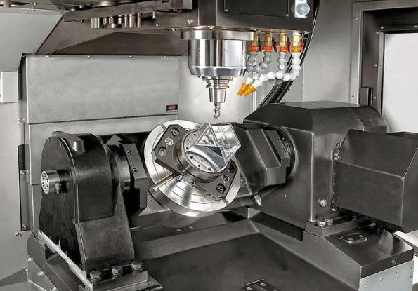
- 5-Axis CNC: Adds two rotational axes (A + B or A + C)—lets the tool approach the part from any angle, making it possible to machine complex shapes like aerospace turbine blades.
To explain “how it works” simply: Imagine a sculptor who can move their chisel in 5 different directions (not just up/down/left/right, but also twisting the sculpture). The CNC system acts as the sculptor’s “brain,” following a digital design to carve the part with extreme accuracy. This flexibility is the core of Multi-Axis CNC Machining—turning complex blueprints into tangible, precise parts.
The Multi-Axis CNC Machining Process
Our step-by-step process is designed to ensure precision, efficiency, and consistency—from design to finished part. Each phase is optimized to minimize errors and meet your specifications:
- Design and CAD Modeling: We start by reviewing your existing CAD (Computer-Aided Design) model or collaborating to create one. Our engineers refine the design for manufacturability—e.g., adjusting undercuts to be accessible by 5-axis tools or simplifying features to reduce machining time. For prototype projects, we offer 3D modeling support to turn sketches into actionable CAD files.
- CAM Programming: The CAD model is imported into CAM (Computer-Aided Manufacturing) software, which generates the tool paths (the cutting tool’s movement). For multi-axis parts, we program rotational axes (A/B/C) to ensure the tool approaches the part from optimal angles—avoiding collisions and ensuring smooth cuts.
- Setup and Calibration: The raw material is secured in a fixture (custom-made for complex parts) on the machine bed. We calibrate the machine’s axes using laser measuring tools to ensure alignment (critical for multi-axis precision). Cutting tools (e.g., end mills, drills) are loaded, and coolant systems are activated to prevent tool overheating and improve surface finish.
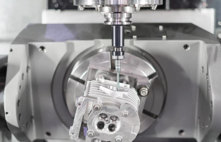
- Machining Execution: The CNC system takes control, executing the programmed tool paths. For 5-axis parts, the machine synchronizes linear (X/Y/Z) and rotational (A/B/C) axes to machine complex features in one setup (no need to reposition the part). Our operators monitor the process in real time to address any issues (e.g., tool wear).
- Post-Machining Inspection: After machining, each part undergoes rigorous inspection. We use CMMs (Coordinate Measuring Machines) to verify dimensions against the CAD model, check surface finish with profilometers, and ensure tolerances are met. Parts requiring finishing move to deburring or polishing steps.
Materials We Work With
Multi-Axis CNC Machining excels with a wide range of materials—from hard metals to lightweight composites. Below is a breakdown of our supported materials, their key properties, and ideal uses:
| Material Category | Examples | Key Properties | Ideal Applications | Machining Notes |
| Metals | Stainless Steel | Corrosion-resistant, strong | Medical implants, food processing equipment | Use high-speed steel tools; coolant reduces heat |
| | Aluminum | Lightweight, conductive, easy to machine | Automotive parts, aerospace frames | Fast cutting speeds; minimal tool wear |
| | Titanium | High strength-to-weight, biocompatible | Orthopedic implants, turbine blades | Slow speeds; carbide tools prevent wear |
| | Brass | Malleable, conductive | Electrical connectors, decorative parts | Fast speeds; produces smooth finishes |
| | Copper | Highly conductive, heat-absorbent | Heat exchangers, wiring terminals | Use coolant to avoid tool overheating |
| Non-Metals | Plastics (ABS/Polycarbonate) | Lightweight, durable, low cost | Electronics casings, prototypes | Low cutting speeds to prevent melting |
| | Composites | High strength, lightweight | Racing car bodies, aerospace panels | Specialized tools to avoid fiber fraying |
| | Wood | Natural, cost-effective | Custom furniture, decorative parts | Sharp tools; vacuum fixtures secure parts |
We test all materials before machining to optimize tool selection and speeds—ensuring consistent quality across every part.
Tolerances & Quality Assurance
Tolerances and accuracy standards are the foundation of our service—we understand that even 微小 (tiny) deviations can ruin complex parts (e.g., aerospace turbine blades). Our precision levels and tolerance ranges are tailored to your material and application, backed by rigorous measurement techniques and quality control processes:
| Material | 3-Axis Tolerance | 5-Axis Tolerance | Accuracy Standard Used | Measurement Technique |
| Stainless Steel | ±0.01mm | ±0.005mm | ISO 2768-1 (fine), ASME Y14.5 | CMM + Laser Scanner |
| Aluminum | ±0.015mm | ±0.008mm | ISO 2768-1 (fine), AMS 2750 | CMM + Digital Calipers |
| Titanium | ±0.012mm | ±0.006mm | ISO 2768-1 (fine), AMS 4928 | CMM + Optical Comparator |
| ABS Plastic | ±0.02mm | ±0.01mm | ISO 2768-1 (medium), ASTM D638 | CMM + Micrometer |
| Composites | ±0.025mm | ±0.015mm | ISO 1288-1, ASTM D3039 | CMM + Profilometer |
Our quality control processes include:
- Pre-machining: Inspecting raw materials for defects (e.g., cracks in titanium, fraying in composites) and verifying dimensions.
- In-process: Real-time monitoring of tool paths and axis alignment via CNC software; periodic checks with calipers/micrometers.
- Post-machining: 100% inspection with CMMs (for multi-axis parts) and surface finish testing; critical parts (e.g., medical implants) undergo additional testing (e.g., stress tests, biocompatibility checks).
Documentation: We provide a detailed quality report with every order, including measurement data, inspection results, and compliance certificates (e.g., ISO 9001, FDA for medical parts).
Key Advantages of Multi-Axis CNC Machining
Compared to traditional 2-axis or 3-axis machining, Multi-Axis CNC Machining offers transformative benefits for complex parts:
- High Precision: 5-axis machines achieve tolerances as tight as ±0.005mm—critical for aerospace/medical parts where fitment and performance are non-negotiable.
- Complex Geometries: Rotational axes enable machining of undercuts, curved surfaces, and 3D features (e.g., turbine blades, orthopedic implants) that would require multiple setups (or be impossible) with fewer axes.
- Reduced Setup Time: Multi-axis machines finish parts in one setup (no need to reposition the part for different features). This cuts setup time by 50–70% compared to 3-axis machining.
- Increased Efficiency: Fewer setups mean less operator time and faster production. For high-volume orders (e.g., automotive parts), this translates to 30–40% shorter lead times.
- Versatility: One machine handles metals, composites, and plastics—so you can use a single service for diverse projects (e.g., a medical device with aluminum frames and plastic casings).
- Cost-Effectiveness: Reduced setup time and fewer errors lower labor costs; one-setup machining reduces material waste (no need to cut extra material for repositioning).
- Consistency and Repeatability: CNC programming ensures every part is identical—critical for mass production (e.g., 10,000 identical brass connectors) or replacement parts (e.g., aerospace components).
Industry Applications
Multi-Axis CNC Machining is used across industries that demand complex, high-precision parts. Here are its most common applications:
| Industry | Common Uses | Axes Most Used |
| Aerospace | Turbine blades, engine components, structural frames (titanium/aluminum) | 5-axis |
| Automotive | Transmission parts, suspension components, custom alloy wheels | 4-axis/5-axis |
| Medical Devices | Orthopedic implants (titanium), surgical tools (stainless steel), device casings (plastic) | 5-axis |
| Industrial Manufacturing | Machine tooling, conveyor system parts, hydraulic valves (steel/brass) | 3-axis/4-axis |
| Electronics | Circuit board enclosures (plastic), heat sinks (aluminum), connectors (brass) | 3-axis/4-axis |
| Defense | Weapon components, vehicle armor parts, communication equipment (steel/titanium) | 5-axis |
| Tool and Die Making | Injection molds, stamping dies, custom cutting tools (steel) | 5-axis |
| Prototyping | Rapid prototypes of new products (plastics, aluminum) | 3-axis/4-axis |
For example, in the medical industry, our 5-axis machining creates titanium hip implants with complex, patient-specific geometries—ensuring a perfect fit. In aerospace, 5-axis turbine blades are machined to tight tolerances to maximize fuel efficiency.
Case Studies: Success Stories
Our Multi-Axis CNC Machining services have helped clients across high-precision industries overcome design challenges and achieve production goals. Below are two successful projects showcasing our expertise in 5-axis machining and custom solutions:
Case Study 1: Aerospace Turbine Blade Manufacturer
- Challenge: The client needed 1,000 titanium turbine blades for jet engines—each with complex curved surfaces, undercuts, and a tolerance requirement of ±0.005mm. Their previous supplier used 3-axis machining, which required 5 separate setups (causing misalignment issues) and a 6-week lead time. The blades also failed fatigue tests due to inconsistent surface finish from multiple setups.
- Solution: We opted for 5-axis CNC machining (simultaneous A+B axes) to machine each blade in one setup—eliminating alignment errors. We used carbide cutting tools (optimized for titanium) and trochoidal milling (a machining technique that reduces tool wear) to maintain precision. High-pressure coolant (100 bar) was used to improve surface finish and prevent tool overheating. Our CAM team also optimized tool paths to reduce cutting time by 30%.
- Results:
- 100% of blades met the ±0.005mm tolerance—alignment errors dropped from 0.02mm (previous supplier) to 0.003mm.
- Fatigue test pass rate increased from 75% to 99% (thanks to consistent surface finish).
- Lead time shortened from 6 weeks to 3 weeks—helping the client meet their jet engine production schedule.
- Client Testimonial: “The 5-axis machined blades are far more consistent than what we got before. The one-setup process eliminated our biggest pain points—misalignment and slow delivery. We’ve now made them our sole supplier for turbine blades.” — Raj S., Aerospace Engineering Director.
- Before and After: 3-axis blades had visible tool marks and inconsistent curves; 5-axis blades featured smooth, uniform surfaces that met aerospace fatigue standards.